How to Make a 3D Printed Injection Mold in 2026?

Making a 3d printed injection mold in 2026 is more practical than it was a few years ago. Better resin systems, stronger printers, and improved simulation tools have changed the workflow. However, printed tooling still requires careful design, controlled processing, and realistic expectations. It is not a magic shortcut.

This guide explains how to plan, model, print, finish, and test a small injection mold. You will see how part geometry affects draft angles, wall thickness, runners, gates, and cooling. A mold cavity may look accurate on a screen, yet tiny surface defects can transfer directly to the molded part. A 0.2-millimeter ridge can become a visible witness line. Small details matter.

Material selection also deserves close attention. Standard resin may work for low-temperature prototypes, while engineering resin can offer better heat resistance and dimensional stability. Still, every material has limits. Injection pressure, cycle time, clamping force, and polymer temperature must match the mold’s design. Published data helps, but real testing remains essential. Actual results vary.

A reliable process includes measuring the printed mold, checking alignment, and inspecting flash after each trial. Use appropriate protective equipment and follow the printer, resin, and injection machine manufacturers’ instructions. This article focuses on responsible prototyping and small-batch development, not unrestricted production claims. Some recommendations may need adjustment. That is part of the learning process. Expect iteration, record each change, and improve the mold through evidence rather than guesswork.
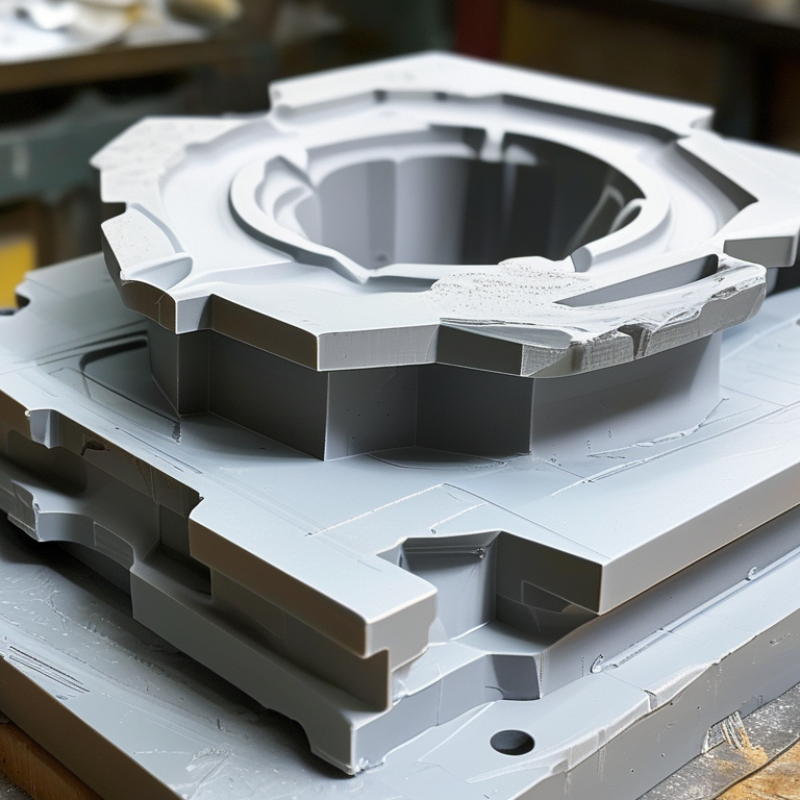
How to Make a 3D Printed Injection Mold in 2026?

Define the Design Requirements for a 3D Printed Injection Mold

Before modeling a 3D printed injection mold, define the production target clearly.

Identify the plastic, expected part quantity, wall thickness, and required surface finish. These choices determine whether printed tooling is suitable for your project.

Record the molding machine’s clamping force, injection pressure, nozzle temperature, and available mold space. Then set realistic limits for the printed material. Resin or polymer tooling may soften, crack, or deform during repeated cycles.

Include draft angles, a practical parting line, vent locations, cooling channels, and an ejection method. Small details matter. A trapped air pocket can leave burn marks, incomplete filling, or a weak corner.

Keep critical dimensions within the printer’s reliable tolerance, not its advertised resolution. A perfect first design is unlikely. Allow time for test shots and adjustment.

Tips:

Use a simple test mold before committing to a complex cavity. Measure the printed cavity after curing, because shrinkage can change the final dimensions. Add generous radii to sharp internal corners.

Plan access for cleaning and inspection. If the part needs a polished appearance, specify how layer lines will be removed before molding.

Document every revision, including temperature, pressure, cycle time, and visible defects. This record supports better decisions and reveals which assumptions were wrong.

A lower cycle count may be acceptable, but only when the tooling goal is clearly defined.

Choose Suitable Materials, Printers, and Mold Components

How to Make a 3D Printed Injection Mold in 2026?
Choose Suitable Materials, Printers, and Mold Components

A reliable mold starts with the resin or filament, not the printer. For short runs, use a heat-resistant photopolymer or reinforced engineering thermoplastic. Check heat deflection temperature, shrinkage, and chemical compatibility with the injection material. A material can survive heat yet crack under clamp pressure. I learned this after a cavity edge chipped during demolding.

Use a printer that can hold tight dimensional tolerances across the entire build plate. High-resolution resin printing suits small cavities and fine textures. Fused-filament printing can work for larger molds, but layer lines need sealing and careful finishing. Print the cavity, core, and alignment features separately when repairs may be needed. Keep walls thick around gates and ejector holes. Thin sections look efficient, until they warp.

Mold components must support safe, repeatable operation. Add steel or hardened inserts at gates, pins, and other wear points. Use alignment pins, bushings, sprue features, and ejector hardware when their dimensions match the design. Venting deserves attention; trapped air can burn the part or cause incomplete filling. Test with low injection pressure and inspect flash, distortion, and surface marks. My early trials relied too heavily on printed threads, and they loosened faster than expected. Metal fasteners worked better, although they complicated assembly. Document every cycle, temperature, and failure before changing the design.

Create and Prepare the Mold Design for 3D Printing

Designing a 3D printed injection mold starts with the part, not the printer. I inspect wall thickness, undercuts, corners, and likely ejection points before modeling. Sharp internal corners can trap plastic and damage the mold. Small radii usually improve filling and reduce stress.

The parting line should follow the simplest release path. I keep it away from visible surfaces when possible. Draft angles are essential, even for short mold walls. A slight angle helps the part leave cleanly.

Add separate inserts for deep features or fragile details. They are easier to replace than an entire mold half.

The cavity and core need controlled clearances. I account for material shrinkage, printer accuracy, and the mold’s working temperature. These values are estimates, not promises. A test coupon can reveal more than a perfect digital model. Include gates, runners, and vents in the design. Vents should lead air away from the final filling area. Tiny vents often clog, so I check them after every trial.

I prefer printing alignment features directly into both halves. They reduce shifting during clamping. The first mold I prepared had attractive details but poor cooling access. It looked successful on the screen. It was not. Now I leave space for cooling channels, inspect wall thickness, and print a low-detail prototype before committing to the final mold.

Print, Assemble, and Finish the Injection Mold

How to Make a 3D Printed Injection Mold in 2026?

Print, Assemble, and Finish

A 3D printed injection mold begins with controlled geometry, not the printer. Add 1–2 degrees of draft to every vertical cavity wall. Keep the parting line simple and easy to inspect. The 2024 Wohlers Report valued additive manufacturing at $20.035 billion in 2023, showing its growing role in practical tooling. Choose a heat-resistant printing material that matches the plastic’s processing temperature. A low-temperature test resin is safer for early trials.

Print both mold halves flat whenever possible. This reduces support marks across the cavity surface. Use alignment pins, clearance holes, and steel bolts during assembly. Leave space for vents near the last filling areas. Tiny vents, around 0.02–0.05 millimeters deep, can reduce trapped air. They are easy to overlook. I would not trust the first print without checking flash, warping, and clamp alignment.

Finish the cavity with progressive sanding, then polish only where appearance requires it. Excessive polishing can change dimensions and weaken sharp edges. Grand View Research estimated the injection molding machine market at approximately $15.4 billion in 2023, reflecting the scale of the process this small tool supports. Begin with modest injection pressure and short cycles. Record temperature, fill time, and defects after every shot. A rough surface may improve release, while a perfectly glossy finish can sometimes hold the part. Testing reveals which assumption was wrong.

Test, Troubleshoot, and Improve the Mold in 2026

How to Make a 3D Printed Injection Mold in 2026?

Testing the mold matters more than printing it quickly. The Wohlers Report 2024 valued the additive manufacturing industry at $20.035 billion in 2023, showing stronger adoption across production workflows. Yet printed molds still fail through heat, pressure, or poor venting.

Begin with a low-pressure trial and record every result. Check flash along the parting line. Inspect short shots near thin ribs. Measure cooling time with a stopwatch, not memory. A 0.2 mm layer height may print cleanly, but it can leave visible texture on the molded surface. Sanding may improve appearance, though it can change cavity dimensions. That mistake is easy to miss.

A practical test uses ten identical shots. Track fill pressure, cycle time, part weight, and key dimensions. Compare the results against the drawing’s tolerance. If weight changes by more than a few percent, inspect temperature control and clamping force. ASTM additive manufacturing guidance also emphasizes process documentation and repeatability, not visual inspection alone. Keep a log.

Troubleshoot one variable at a time. Increase vent depth carefully. Reinforce weak corners. Reduce injection speed when the cavity shows burning. I once blamed the polymer for a warped part; the real cause was uneven cooling. The lesson remains uncomfortable. A printed mold is a test system, not a shortcut. Reprint only after the evidence points to a design change.

How to Make a 3D Printed Injection Mold in 2026? - Test, Troubleshoot, and Improve the Mold in 2026

Stage Data Dimension Typical Target or Range Recommended Test Common Failure Sign Likely Cause Improvement Action
Design Part draft angle At least 1° per side; 2° or more for textured surfaces Inspect the CAD model and confirm the pull direction before printing Part sticks to the cavity or requires excessive ejection force Insufficient draft, shrinkage around vertical walls, or surface texture Increase draft, polish the pull direction, and add a controlled ejector layout
Design Minimum wall thickness of printed mold Normally 8–12 mm around the cavity for low-pressure trials; use more support for larger parts Measure the CAD wall section and check for unsupported spans Mold flexing, cracking, or flash along the parting line Thin mold walls, weak print orientation, or insufficient backing support Thicken the mold, add a rigid frame or backing plate, and orient layers away from the main opening force
Printing Dimensional accuracy Typical resin-printing tolerance: about ±0.05–0.20 mm, depending on geometry and process Measure critical cavity dimensions with calibrated digital calipers or a gauge Part is oversized, undersized, or the two mold halves do not align Print shrinkage, incorrect compensation, support marks, or printer calibration error Calibrate exposure and dimensional scaling, then apply measured compensation in the CAD model
Printing Layer height and surface quality About 0.025–0.100 mm layer height for detailed resin molds; finer layers improve surface finish Inspect the cavity under magnification and compare roughness across the parting line Visible stepping, drag marks, or patterned defects on the molded part Layer lines, poor support placement, overexposure, or inadequate post-curing Use a finer layer height, move supports away from the cavity, and wet-sand or polish non-functional surfaces
Post-Processing Post-cure condition Follow the material supplier's time and temperature limits; under-cure leaves the mold soft, while over-cure can increase brittleness Check hardness, tackiness, dimensional change, and visible cracking after washing and curing Cavity deformation, sticky surfaces, or cracks during clamping Incomplete solvent removal, incorrect cure cycle, or resin heat resistance below the process requirement Use the documented cure cycle, allow complete drying, and select a mold material with adequate heat-deflection performance
Mold Assembly Parting-line alignment Target mismatch: preferably below 0.10 mm on critical edges Close the empty mold and check alignment with feeler gauges or transfer marking Flash, offset edges, or an uneven witness line Misplaced registration pins, warped halves, or debris on the parting surface Add robust alignment features, clean both faces, and reduce clamping distortion
Injection Setup Material selection Begin with lower-temperature, low-shrinkage thermoplastics such as polyethylene or polypropylene for early trials Confirm melt temperature, mold temperature, drying requirements, and shrinkage in the material data sheet Mold softening, burning, incomplete filling, or excessive shrinkage Material temperature or pressure exceeds the printed mold's capability Use a compatible polymer, reduce process severity, and avoid high-temperature engineering materials during initial testing
Injection Setup Injection pressure Start with the lowest pressure that fills the cavity; use short-shot trials before increasing pressure Run a sequence of partial fills and record pressure, fill percentage, and visible mold movement Flash, mold separation, cracks, or sudden dimensional changes Excessive injection pressure, restricted gate, or inadequate clamping support Enlarge the gate or runner, reduce injection speed and pressure, and reinforce the mold externally
First Test Short-shot filling pattern The flow front should advance evenly without a premature frozen region Stop at approximately 50%, 75%, and 90% fill to identify the last area to fill Unfilled corners, weld lines, or trapped air near the end of fill Gate too small, venting too limited, melt too cold, or flow path too long Improve venting, enlarge the gate, raise melt temperature within the material limit, or shorten the flow path
Troubleshooting Flash thickness Aim for no visible flash; a thin, repeatable flash below about 0.05 mm may be removable in prototype work Measure the flash with a microscope or thin feeler gauge after each process change Thin fins of plastic along the parting line or around ejector features Insufficient clamping, damaged parting surface, excessive pressure, or mold deflection Lower pressure, improve support, flatten the parting face, and remove debris before clamping
Troubleshooting Warping and shrinkage Compare part dimensions after cooling; molded thermoplastics commonly shrink approximately 0.5–2.5%, depending on polymer and geometry Measure length, width, and flatness at a consistent time after molding Curved surfaces, sink marks, or dimensions changing after ejection Uneven cooling, excessive packing, variable wall thickness, or incorrect shrinkage compensation Balance wall thickness, reduce packing, improve cooling consistency, and compensate dimensions using measured results
Troubleshooting Venting depth Prototype vents are commonly shallow, around 0.02–0.05 mm, and should be placed at the final fill locations Inspect burn marks and compare fill results before and after adding vents Burn marks, hesitation, voids, or incomplete filling at the end of the flow path Compressed air cannot escape from the cavity Add shallow vents to the parting line, improve air channels, and avoid deep slots that may create flash
Improvement Cycle life Plan for approximately 10–100 shots for many printed prototype molds; actual life depends on material, pressure, temperature, and geometry Record shot count and inspect the cavity, parting line, gate, and alignment features after every test batch Progressive cracking, dimensional drift, surface wear, or increasing flash Thermal cycling, mechanical stress, abrasion, or repeated ejection loads Reduce pressure, use replaceable inserts, add radii at stress concentrations, and redesign high-wear areas
Improvement Process repeatability Use the same material batch, drying state, mold temperature, injection speed, and cooling time for comparison tests Log at least 5 consecutive shots and compare mass, dimensions, flash, and visual defects Every part looks different despite unchanged settings Uncontrolled material moisture, inconsistent heating, mold movement, or changing cooling time Create a fixed test procedure, use a shot log, stabilize the mold before measurement, and replace the mold when drift becomes unacceptable

Note: The values are practical prototype ranges. Always verify the printed mold material's heat-deflection temperature, strength, chemical resistance, and the molding material's processing data before testing.