Best 3D Printed Injection Mold for 2026?

A 3d printed injection mold can shorten the path from CAD file to molded sample, but it is not a universal shortcut. Its value depends on resin, part geometry, cooling needs, and expected production volume. A compact mold insert may suit a short validation run. A thin rib, deep core, or uneven cooling channel can expose weaknesses quickly. The details matter.

The Wohlers Report 2024 estimated that the global additive manufacturing industry reached $20.035 billion in 2023, growing 11.1% year over year. That figure covers the broader AM industry, not 3D-printed tooling alone. It signals momentum, not proof that printed molds outperform machined steel in every application. Terry Wohlers, an established additive manufacturing analyst, offers a useful principle: additive manufacturing should be judged by the production problem it solves, not by novelty. This is a paraphrase of his industry perspective, not a verbatim quotation.

For 2026, the best mold is therefore not simply the fastest or cheapest to print. It must deliver acceptable surface finish, dimensional consistency, cooling performance, and tool life for the intended run. Small trials can reveal problems that a polished rendering hides. That part deserves scrutiny. This guide compares mold materials, printing processes, costs, and practical limits, while distinguishing published industry data from mold-specific performance claims. The goal is a grounded choice, not a promise of effortless production.
Best 3D Printed Injection Mold for 2026?

What Is a 3D-Printed Injection Mold?

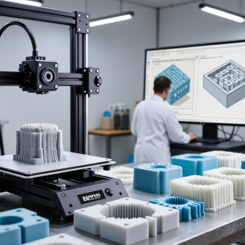
A 3D-printed injection mold is a cavity and core made layer by layer, then fitted into a mold base. Molten plastic enters the cavity, cools, and takes its shape. The printed insert may be polymer-based or metal, depending on the process and intended production conditions. It is not simply a plastic mold made on a desktop printer; material choice, print direction, finishing, and machine setup all affect performance.

These molds are often useful for checking a part’s shape, fit, and function before investing in hardened tooling. A printed insert can include small channels or complex contours that are difficult to machine. But heat and injection pressure can wear or deform some printed materials, so part count and cycle time need realistic testing. Cooling may also be uneven, leaving a part slightly warped or slower to release. That trade-off is easy to underestimate. A careful trial should record the resin, machine settings, cycle time, and visible defects. Even then, results can vary between machines and materials. A 3D-printed mold is a practical tool for specific, limited jobs, not a universal replacement for conventional production tooling.

How 3D-Printed Injection Molds Are Designed and Made

Best 3D Printed Injection Mold for 2026?
How 3D-Printed Injection Molds Are Designed and Made

Design begins with the part, not the printer. Engineers model the cavity and core, then account for resin shrinkage, draft angles, gate position, and ejection. A tiny trapped air pocket can leave a burn mark; poor venting can also prevent a cavity from filling. Small details matter. Cooling channels should remove heat evenly. Conformal channels can follow the part’s shape, though they add design and inspection challenges.

The Wohlers Report 2024 estimated that global additive manufacturing revenue reached $20.0 billion in 2023, an 11.1% increase from 2022. That figure shows a growing production technology, not proof that every printed mold will last. Mold inserts may be made by polymer printing or metal additive manufacturing, depending on material, pressure, temperature, and expected shot count. The choice needs testing.

After printing, teams remove supports and finish critical surfaces. They check dimensions, polish the cavity, and verify that vents and cooling paths are clear. Then they run trial shots, watching for flash, short fills, sticking, and uneven cooling. A printed insert can speed up low-volume trials, but wear and heat can limit its life. One weak point is often overlooked: the part may fit the drawing yet still cool unevenly. That is why measured cycle times and repeated inspections matter more than appearance alone.

Best 3D-Printed Injection Mold for 2026? Material Thermal Conductivity

Approximate room-temperature thermal conductivity of materials used in injection-mold tooling. Higher conductivity can help remove heat faster, but the best mold depends on part geometry, resin, cooling design, and required production volume.

Printed photopolymer molds can be useful for prototyping and short runs. Metal tooling, including additively manufactured metal inserts, generally offers higher thermal conductivity. Actual values vary by alloy, material formulation, and manufacturing process.

Which Materials and Printing Methods Suit Mold Inserts?

A mold insert’s material should match the molding resin, part geometry, and expected number of cycles. High-temperature photopolymer resin, made with SLA or DLP printing, can capture fine ribs and smooth surfaces. It suits early trials and short runs, but heat resistance and strength vary by formulation. Check the supplier’s data, then test under your actual molding conditions. A glossy cavity helps, but it does not guarantee easy release.

For tougher inserts, SLS-printed nylon can handle complex shapes, though its slightly porous surface may need sealing or machining. FDM can produce larger, economical inserts, but layer lines may mark the part and weaken thin features. Metal powder-bed printing offers greater durability; machining the cavity afterward can improve accuracy. It costs more. There is no universal winner. Include vents, cooling paths, and a sturdy backing in the design, then inspect the parting line for flash after a small trial. One lesson is easy to miss: printed inserts can deform gradually, not just fail suddenly. Track cycle count and surface wear, and be ready to revise the design.

How to Evaluate the Best 3D-Printed Injection Mold for 2026

Evaluating the best 3D-printed injection mold for 2026 starts with the part, resin, and expected production volume—not a printer specification. Check whether the printed insert tolerates the resin’s processing temperature and injection pressure. Then inspect the design for thin walls, sharp corners, and trapped-air pockets. These details can cause short shots, flash, or early cracking.

Start with evidence. Run a small trial using the intended resin, and record cycle time, part dimensions, and visible defects. A few dozen consistent shots may suit a prototype; longer runs demand stronger wear and heat resistance. Look closely at cooling channels and vents: a hot spot near a thick rib can distort parts, while a blocked vent leaves burn marks. Compare the results with a machined-tool baseline when possible. Small details matter.

Cost alone can mislead. Include insert replacement, finishing, rejected parts, and setup time in your estimate. Ask for material data and test conditions, not just a maximum-shot claim. One trial can also mislead if the machine settings change between runs. That matters. A sensible evaluation weighs repeatability, part quality, and intended volume together; the cheapest mold may not be the most dependable.

Best 3D Printed Injection Mold for 2026? — How to Evaluate the Best 3D-Printed Injection Mold for 2026

Compare mold-making approaches against part requirements, production volume, resin, machine conditions, and validation needs.

Practical comparison of 3D-printed injection mold options
Mold approach Typical mold material Best suited for Heat and process considerations Likely advantages Key limitations to evaluate
Vat-photopolymer printed mold High-temperature photopolymer resin, usually printed as a cavity insert or mold half Prototype parts, design checks, and short trial runs with carefully selected resins and process settings Check the resin’s heat-deflection data, actual mold temperature, injection pressure, and curing requirements. Published heat-deflection values are test-dependent and are not a guaranteed operating limit. Can produce fine surface details and complex cavity geometry without conventional mold machining Heat, pressure, and repeated clamping can cause wear, cracking, or dimensional change. Mold life varies substantially with geometry and process conditions.
Material-extrusion printed mold High-temperature engineering thermoplastic, commonly used for experimental or low-pressure tooling Low-risk trials, large or simple cavities, and applications where printed layer structure is acceptable Layer direction, build settings, material conditioning, and thermal cycling affect strength. Confirm that the material and printed construction tolerate the intended mold temperature and loading. Accessible workflow, relatively quick design changes, and potential for integrated channels or fixtures Layer lines may transfer to the part; anisotropy, porosity, and limited surface finish can affect sealing, strength, and appearance.
Metal additive-manufactured mold insert Metal powder processed into an insert, with finishing and machining as needed More demanding tooling where metal strength, durability, or conformal cooling may justify the added process steps Evaluate alloy, heat treatment, density, residual stress, and post-processing. Cooling performance depends on channel design and the complete mold setup. Can support more robust tooling than polymer inserts and may enable cooling-channel geometries that are difficult to machine conventionally Requires qualified metal processing, inspection, finishing, and integration with a mold base; cost and lead time can exceed polymer tooling.
Hybrid printed-and-machined mold Printed insert or core combined with a conventional mold base, machined shutoffs, or metal supports Prototypes and bridge tooling that need printed geometry but benefit from accurately machined interfaces Check insert retention, parting-line fit, venting, cooling, and alignment. The printed portion must be compatible with the load and temperature at its location. Combines design flexibility with established mold-base components and can limit printing to complex features Interface design and assembly are critical; poor support or fit can lead to flash, movement, or premature insert failure.
Conventional machined metal mold Machined aluminum or tool steel Repeated production, tighter process control, and applications needing established tooling performance Choose the material and mold design based on resin, abrasiveness, cycle conditions, required finish, and expected production volume. Well-established design, finishing, and maintenance practices; suitable for a wide range of production requirements Tooling may take longer or cost more to change than a printed prototype mold, especially during early design iterations.
Evaluation checklist for selecting a mold
Evaluation dimension What to verify How it affects the decision
Resin compatibility Resin processing temperature, shrinkage, flow behavior, abrasiveness, and any moisture-drying requirements Some resins and processing conditions are more demanding on a printed mold than others. Confirm compatibility with the mold material and process.
Production quantity Expected shots, required repeatability, and acceptable maintenance or replacement frequency Printed polymer tooling is generally considered for prototypes and short runs; the suitable quantity is application-specific and should be validated with trials.
Geometry and draft Parting line, draft angles, undercuts, wall thickness, gates, vents, and ejection strategy Good mold design can improve filling and release. Complex geometry may favor additive manufacturing, but printing does not remove the need for sound mold design.
Surface and dimensional requirements Required surface texture, critical dimensions, tolerances, and post-processing plan Printed resolution is not the same as finished-part accuracy. Allow for finishing, shrinkage, and process variation where dimensions are critical.
Machine and operating conditions Clamp force, injection pressure, mold temperature, cooling arrangement, and machine compatibility Use the actual machine and process window to assess loading. Do not treat a material data-sheet temperature as proof that a mold will survive production conditions.
Validation plan Trial shots, dimensional inspection, leak or flash checks, cycle monitoring, and inspection intervals A controlled trial is the most reliable way to establish achievable quality and practical mold life for a specific part and process.
Total project cost Design iterations, printing or machining, finishing, mold-base integration, trial time, and replacement risk Compare the full path to acceptable parts—not just the initial mold-making cost.

Important: There is no single best 3D-printed injection mold for every application. Performance and service life depend on mold material, geometry, resin, machine settings, cooling, finishing, and maintenance. Treat any shot-count or temperature estimate as application-specific unless supported by testing under the intended conditions.

Where 3D-Printed Injection Molds Work and What Limits Them

A printed injection mold can make sense when a team needs a few molded parts before committing to metal tooling. It is especially useful for checking fit, assembly, and basic function. A short run of small plastic clips or enclosure parts can reveal problems that a printed prototype may hide. Useful, but limited.

The mold’s resin, geometry, and printer settings all affect how it handles heat and injection pressure. Thin cores, sharp corners, and long flow paths can fail early or produce uneven parts. A cautious trial uses conservative settings and checks the mold after each cycle. Watch for cracks, softened surfaces, flash, and blocked vents. These details matter.

Cycle life is not a fixed number. It changes with the mold material, part design, resin, and machine settings, so test data from one setup may not transfer to another. Printed tools can also have rougher surfaces and less effective cooling than machined steel molds. That trade-off is easy to underestimate. They are not a shortcut to mass production; they are a practical option for limited runs, provided the expected output and material limits are clear.